'Missile' Launcher – Multiple Rocket Launcher
Quick Facts
| Date: | September 2023 - May 2024 |
|---|---|
| Cost: | ~$2000 |
This project is an ‘erector-launcher’; a machine capable of automatically turning and elevating (erecting) a rocket for launch. The goal of this project was to build such a machine for model rockets, able to lift and aim one or more rockets for launch, inspired by military Transporter-Erector-Launchers (TELs). When launching model rockets, a simple rail or rod is used to hold the rocket. However, this rod must be ideally vertical to the ground or aimed at a precise angle to compensate for windy conditions. The machine I aimed to build would be able to do so automatically and precisely.
This project had very exacting requirements. The primary concern with such a device is safety. If built too weak, the rocket could fall over during launch, which could possibly lead to it being fired at people or objects nearby, or lead to people being caught in the exhaust and burned. To avert this possibility, I assigned a minimum weight limit to the device. It needed to be capable of turning and elevating at least 150lbs and be resistant to back driving up to 300lbs. Model rockets typically do not exceed more than a few pounds, so I deemed this weight limit more than sufficient to launch even the heaviest model rockets.
In the event of a power failure, the launcher needed to know its position even after reset, to avoid having to recalibrate its sensors. For that reason, I chose to build the rotation mechanism using a DC motor with gearbox, and a separate, absolute-position encoder to report the device’s azimuthal position. A second encoder was attached to the elevation arm. Each encoder is used by the motor controller to direct power to the DC motor and linear actuator based on a PID feedback loop. Another constraint was the desire to allow for continuous 360-degree rotation. This meant that slip rings had to be used inside the device for all power or data passing from the base to the upper platform. This posed a major challenge as two concentric slip rings were needed, one for the high-current motor lines and rocket ignition circuit, and another for the low-current but more numerous data wires.
The final specification was that power to the rocket igniter and electronics had to be kept separate, for safety reasons. This permits the use of an external interlock controlling rocket ignition power, while still allowing the device to elevate for launch safely. The machine was therefore designed with two separate power inputs, one for the launcher’s own power and controls, and a second that passes straight to the upper platform to an external wire mount, where it can be wired to the rocket’s igniter. Finally, six wires were provided for use by any rocket sensors or data that might require pass-through to a ground computer. These wires pass through the launcher from its base up to the upper rotating platform.
To minimize last-minute design changes, I decided to model the mechanical structure entirely in CAD to try and catch any unforeseen issues before I ordered parts While this did take up a considerable amount of time (almost an entire semester!), it proved invaluable. I was able to determine many specific parameters or constraints during the design phase, rather than find out after already buying parts. Another use of simulation tools to ease development was during the coding and tuning of the PID control loops. Each motor (the DC motor driving the rotation and the linear actuator driving the elevation) had a microcontroller linked to an encoder to run the control loop. These were in turn connected to the launcher’s main controller. To verify that the control loops would work before I built the device, I wrote a piece of software to simulate the motion of the device with a control loop trying to change its position. This helped considerably; I was able to fine-tune the PID parameters and fix numerous issues with the angle calculations.
Owing to my careful use of modeling and simulation tools and testing of individual systems, the design overall worked virtually flawlessly when constructed. That’s not to say there weren’t unforeseen issues that I had to fix, there were several. None of them required any major design change.
In the end, I never got to conduct a proper test of the device because Boston is scarce in suitable rocket launch sites. I tested the weight capacity of the device by standing on it and letting it spin and lift me like a dentist's chair. After graduation however, I shipped it back to Washington and donated it to an old teacher of mine for him to use with his students.
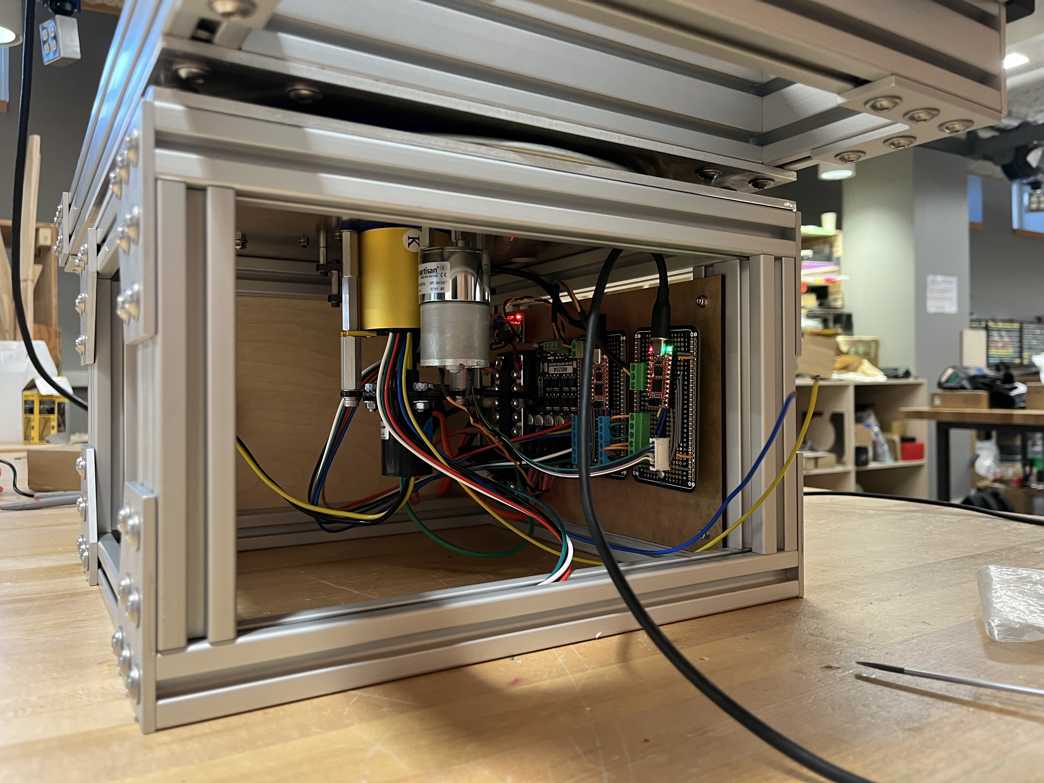
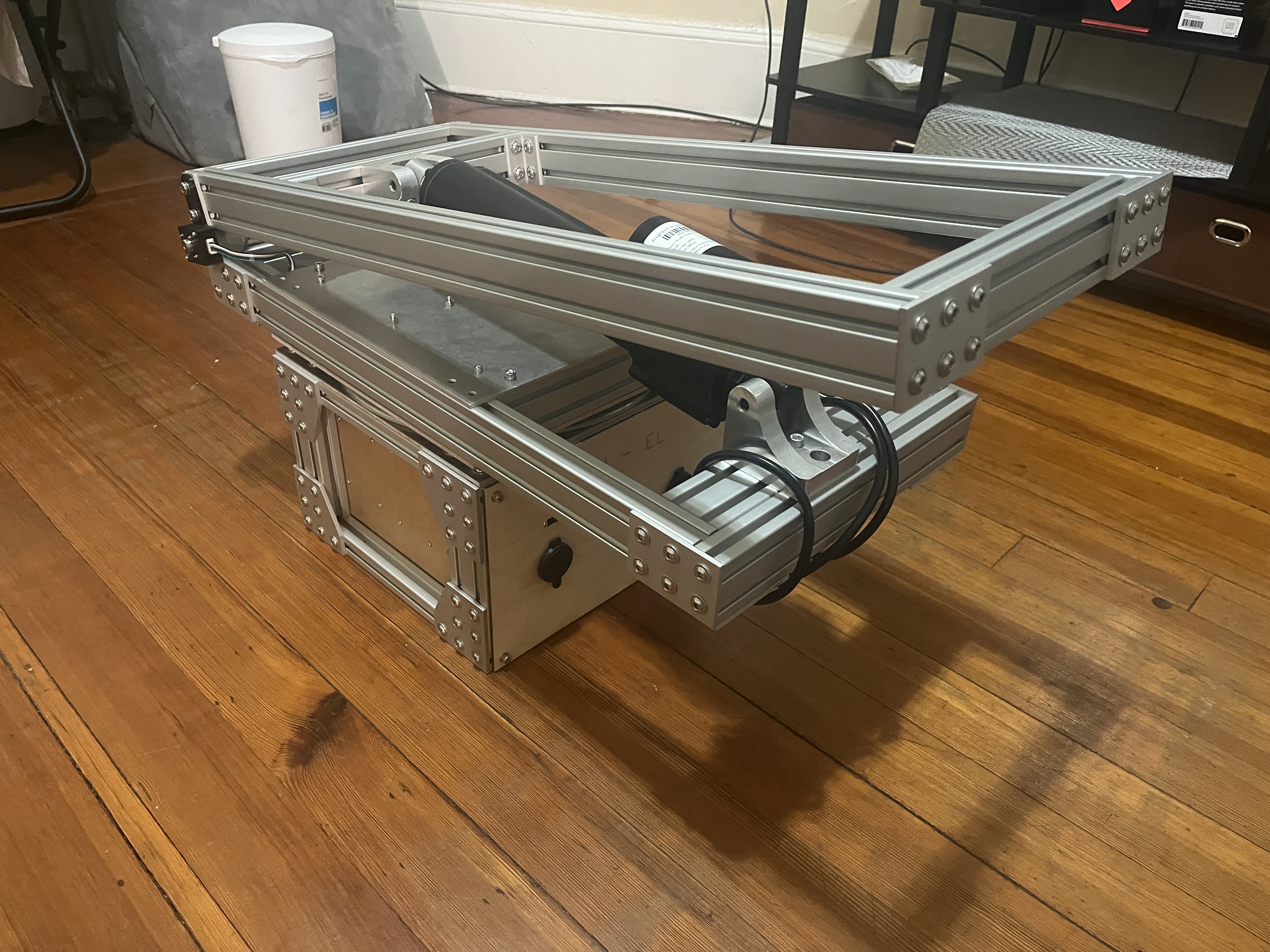
The main electronics and drive system can be seen in Fig. 1. These include the coaxial (gold) and high-current (black) slip rings; the DC gearmotor (silver), and the control board. The encoder and its gearbox are located behind the coaxial slip ring, on the opposite side from the DC motor.
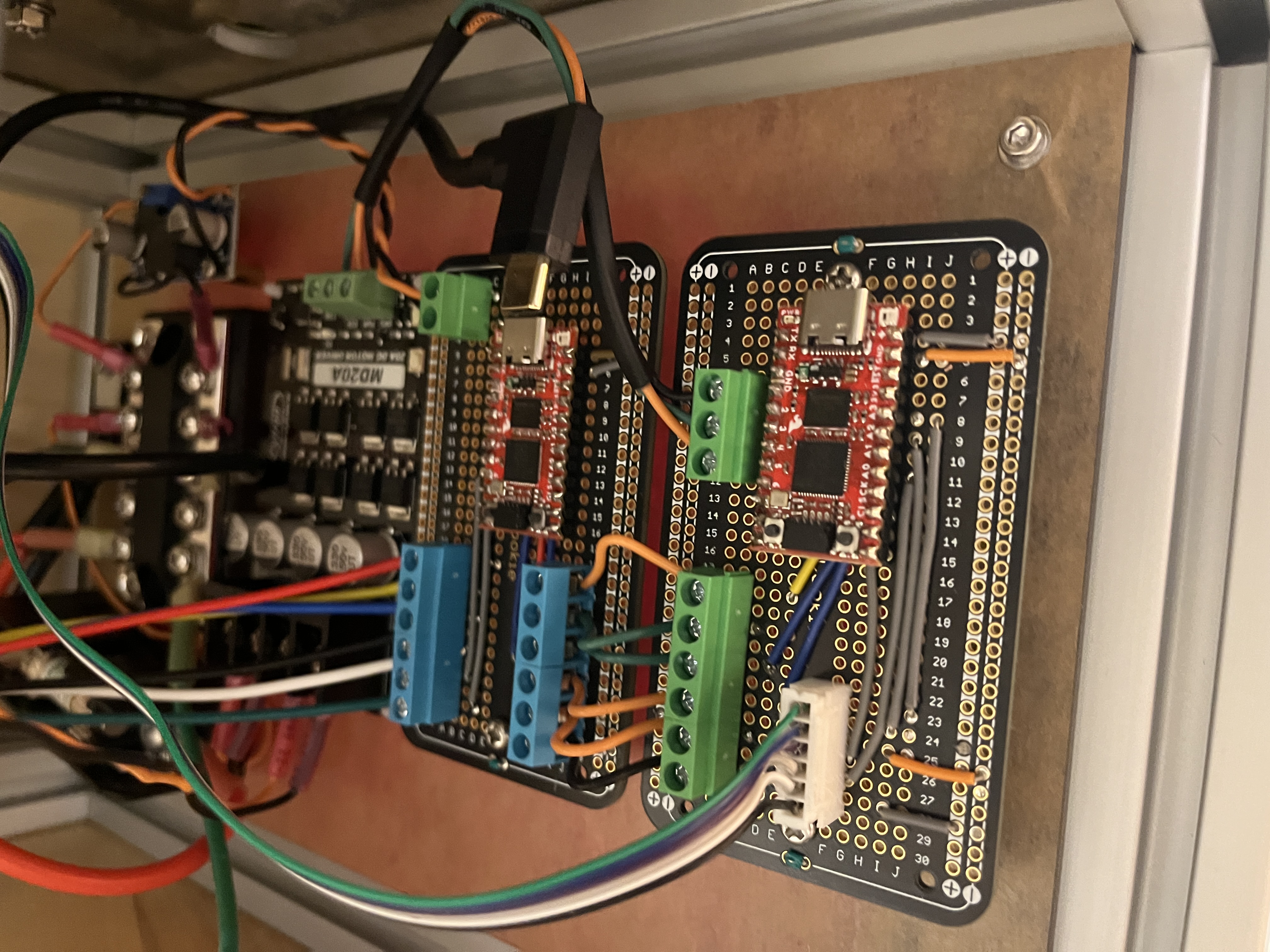
The main electronics (Fig. 2) include the power distribution board (far left); low-voltage buck converter (left top); motor driver (left); the main controller (center); and the rotation motor controller board (right). Each controller board interfaced with the motor driver via PWM and with the position encoder via SPI, then communicated with the main controller over a separate SPI bus.
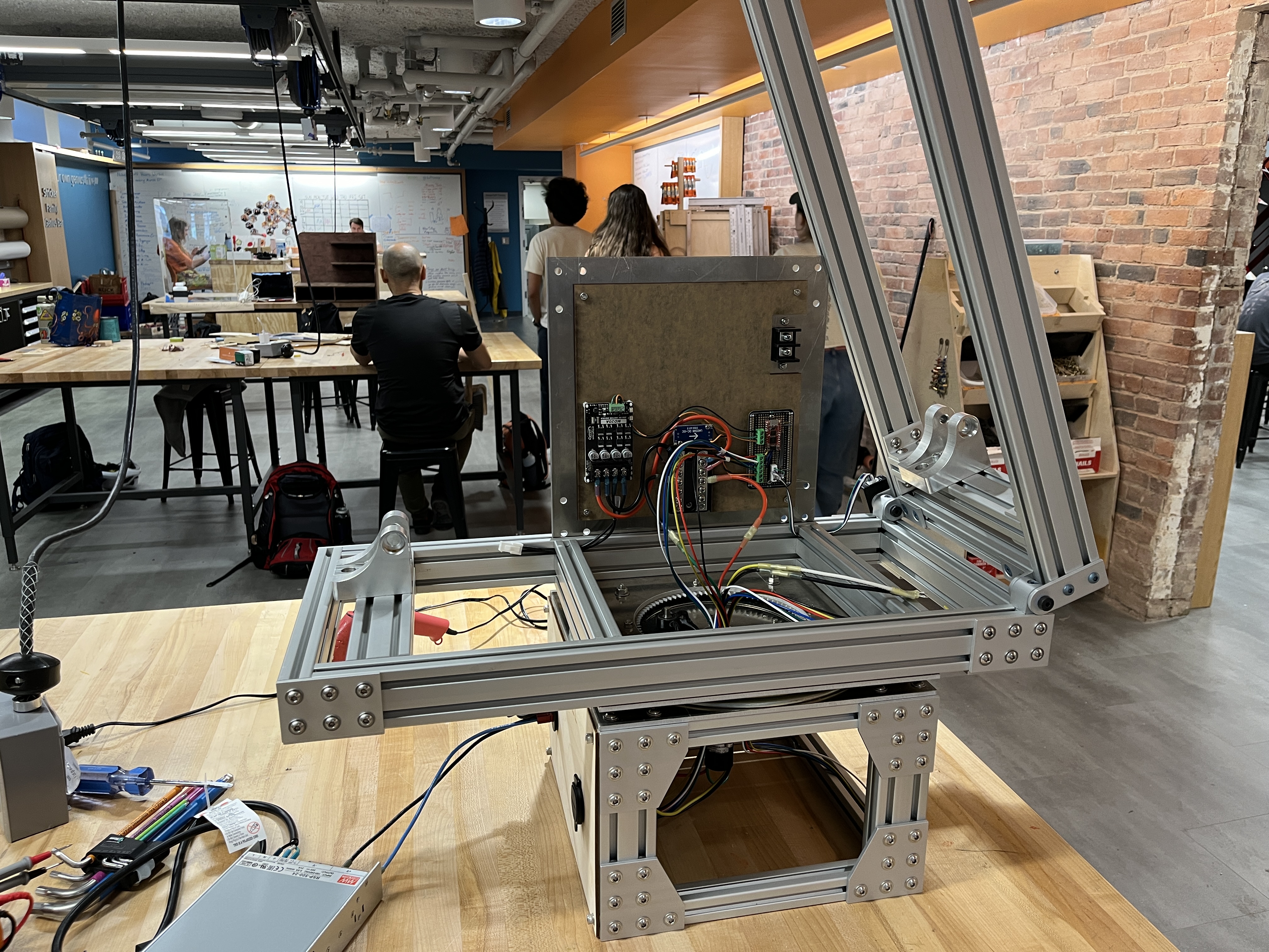
The top compartment of the device (Fig. 3) contains the inner aluminum gear, along with the top electronics: the motor driver (left), power distribution board (center), and elevation motor controller (right). At the top of the panel the rocket ignition pass-through terminal block is visible.
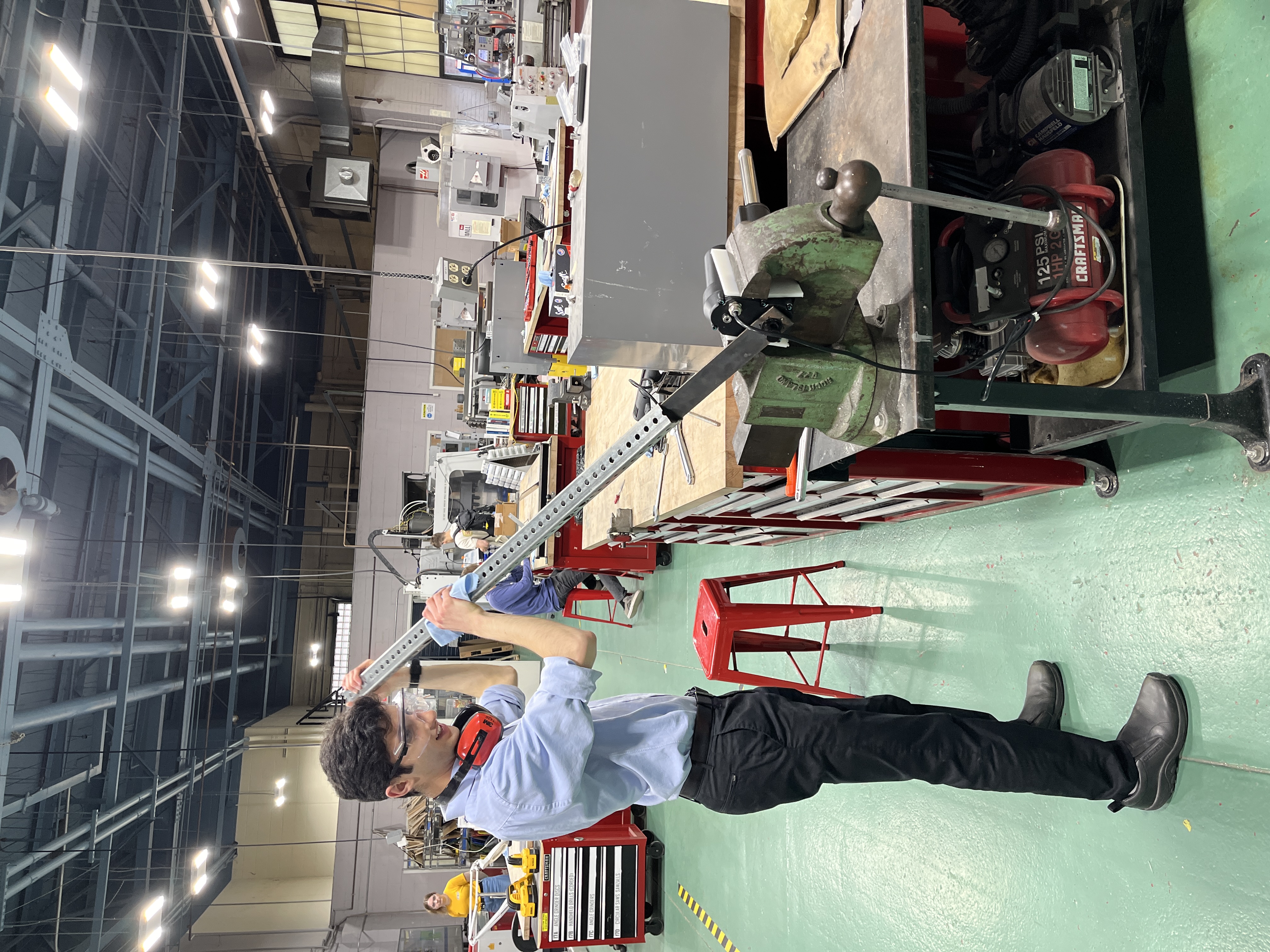
The linear actuator that adjusts elevation arrived with its mounting points shifted by 90 degrees from where I needed it aligned. The manufacturer sent instructions to rotate them to my desired position. As part of this process I needed to remove the back cover of the actuator, which didn't budge from a 12-inch wrench or an 18-inch wrench plus a sledgehammer-wielding shop assistant. To remove this stubborn nut we ended up waterjet-cutting our own socket wrench (none of ours were large enough) out of plate steel then using a breaker bar as a lever to finally turn it.